Để cài đặt biến tần HpMont HD09-2s0p7GMS, bạn cần thực hiện theo các bước chung sau:
Chuẩn bị trước khi cài đặt
– Đảm bảo đã đọc kỹ hướng dẫn sử dụng của biến tần.
– Kiểm tra nguồn điện, dây dẫn, và các thông số của động cơ mà bạn sẽ điều khiển. Đảm bảo chúng phù hợp với thông số của biến tần.
– Kiểm tra không gian lắp đặt biến tần: Nên lắp đặt ở nơi thoáng khí, tránh nhiệt độ quá cao, bụi bẩn hoặc độ ẩm cao.
Kết nối nguồn điện
– Nguồn cấp thường là 1 pha 220V hoặc 3 pha 380V tùy biến tần.
– Kết nối nguồn vào: Nối dây điện nguồn vào các chân L và N (với 1 pha) hoặc R, S, T (với 3 pha).
– Kết nối đầu ra: Nối dây dẫn từ biến tần ra động cơ vào các chân U, V, W trên biến tần.
Kết nối các tín hiệu điều khiển
– Có thể kết nối các tín hiệu điều khiển vào các cổng Analog Input, Digital Input và Relay Output tùy theo yêu cầu điều khiển. Cài đặt tín hiệu điều khiển thường qua các chân như X1, X2, Y1,…
– Kết nối với màn hình điều khiển hoặc module điều khiển từ xa nếu cần.
Cài đặt thông số biến tần
– Khởi động biến tần và cài đặt các thông số cơ bản như tần số, điện áp, dòng điện,… phù hợp với động cơ và ứng dụng.
– Thông thường, bạn cần vào chế độ cài đặt (setup mode) trên màn hình điều khiển và điều chỉnh các tham số theo yêu cầu:
– P0-00: Tần số tối đa.
– P0-01: Tần số khởi động.
– P0-02: Chế độ điều khiển (V/f hoặc Sensorless Vector Control).
– P1-00 đến **P1-15: Cài đặt về dòng điện và điện áp cho động cơ.
Chạy thử nghiệm
– Sau khi cài đặt xong, khởi động biến tần và thử nghiệm động cơ ở tần số thấp để kiểm tra kết nối và thông số cài đặt.
– Tăng dần tần số lên để đảm bảo rằng biến tần hoạt động ổn định với tải.
Kiểm tra bảo vệ và an toàn
– Kiểm tra các chế độ bảo vệ của biến tần như bảo vệ quá tải, quá dòng, quá nhiệt,…
– Nếu biến tần báo lỗi, kiểm tra mã lỗi trên màn hình và đối chiếu với hướng dẫn sử dụng để khắc phục.
Lưu ý: Các thông số trên chỉ mang tính chất tham khảo, bạn cần tham khảo tài liệu của nhà sản xuất hoặc kỹ sư điện có kinh nghiệm để cài đặt chính xác cho ứng dụng cụ thể của bạn.
Cách cài đặt chạy với biến trở ngoài
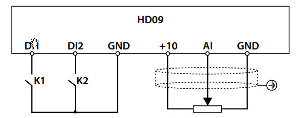
F00.8 cài tần số cao nhất 50hz
F009 Cài tần số thấp nhất 0hz
F00.10 chọn 3
F00.11 chọn 1
F01.02 chọn 1 để sét về mặc định nhà sản xuất
Mặc định chạy và chỉnh tần số trên bàn phím
| Ref. Code | Function Description | Setting Range [Default] |
| F00.06 | Max.output frequency | 50.0 – 1000.0 [50.0Hz] |
| Define converter max. permissible output frequency. • Shall be setted reasonably in according with motor nameplate and actual running situation. |
||
| F00.08 | Maximum operating frequency | 0.0 – F00.06 [50.0Hz] |
| F00.09 | Minimum operating frequency | 0.0 – Max.frequency [0.0Hz] |
| F00.10 | Frequency setting access selection | 0 – 4 [0] |
| 0: Keypad digital setting. 1: Terminal digital setting. 2: SCI communication setting. 3: Analogue setting. 4: Terminal impulse setting. |
||
| F00.11 | Operation command access selection | 0 – 2 [0] |
| 0: Keypad operation command 1: Terminal operation command. 2: SCI communication command. |
||
| F00.13 | Original operation frequency digital setting | 0.0 – Max.frequency [50.0Hz] |
| F00.14 | Frequency setting control | 0000 – 1111 [1001] |
| Enable only when F00.10 = 0,1. When F00.13 is changed, the new value will replace current setted frequency. Units: Selection of frequency save when power off • 0: No. • 1: Save. Tens: Setted frequency when stopping • 0: Keep setted frequency in stopping • 1: Recover to F00.13 in stopping. Hundreds: Selection of frequency save when communicating • 0: No. • 1: Save. Thousands: Selection of frequency save when change frequency access • 0: No. • 1: Save.When frequency setted access is changed from keypad to terminal digital and back to keypad, the keypad frequency is still keeping the last changed frequency. |
||
| F00.15 | Inching operation frequency digital setting | 0.0 – Max. frequency [5.0Hz] |
| F00.17 | Running direction selection | 0,1 [0] |
| 0: Same direction. 1: Contrary direction. |
||
| F00.19 | Dead time between positive and negative rotation | 0.0 – 3600.0 [0.0s] |
| Define transient time when output frequency is 0 in rotation. | ||
| F00.20 | External keypad enable | 00 – 21 [00] |
| Units: Buttons enable • 0: Enable. When convertere is connected with keypad, button operating can be done • 1: Invalid. When convertere is connected with keypad, button operating can not be done. Tens: Potentiometer enable • 0: External keypad potentiometer precedence. When converter is connected with keypad via communication interface, its input voltage is right in keypad. After removing external keypad, voltage is right in its own keypad. • 1: Build-in keypad potentiometer. When converter is connected with keypad via communication interface. Potentiometer input voltage is right in build-in keypad and external one’s potentiometer is invalid. • 2: External keypad potentiometer. When converter is connected with external keypad via communication interface. Potentiometer input voltage is right in external keypad and build-in one’s potentiometer is invalid. |
||
| F00.21 | Hibernation function enable | 0 – 2 [0] |
| 0: Forbidden. This function is invalid. 1: Enable 1. Under running status, when setted frequency ≤ Min.running frequency (F00.09), after hibernating delay time (F00.24), converter will stop freely and enter into hibernating status. 2: Enable 2. Under running status, when setted frequency ≤ hibernating frequency (F00.25), after hibernating delay time (F00.24), converter will stop freely and enter into hibernating status. |
||
| F00.22 | Hibernation awaking time | 0.0 – 360.0 [0.0s] |
| When converer is in hibernation status and setted frequency > Min. running frequency (F00.09) or hibernating frequency (F00.25), besides, sustaining time reaches F00.22 setted time. Converter will awake up and work from hibernating status. |
||
| F00.24 | Hibernating delay | 0.0 – 3600.0 [0.0s] |
| F00.25 | Hibernating frequency | 0.00 – Max. frequency [0.50Hz] |
| F01.02 | Function code parameter initialization (parameter download) | 0 – 4 [0] |
| 0: No action. 1: Restore the factory parameter. 2: Cope the storaged parameter 1 of keypad to controller board for current function code value updating. 3: Cope the storaged parameter 2 of keypad to controller board for current function code value updating. 4: Clear out fault records. Clear out the recorded fault information in F20.21 – F20.33 Note: 1. F01.00, F01.02, F01.03, group F08, F19.19, F19.24, F20.21 – F20.37, F23.00 and group y not be copied. 2. Parameter copying is valid only in external keypad |
• Restore the factory parameter: Set F01.02 = 1, press and it is restoring the factory parameter
when “rESEt” displayed on keypad.