")
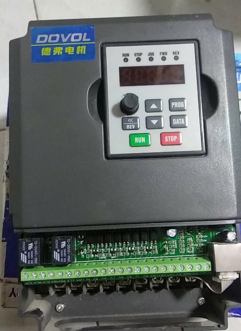
Biến tần DoVoL DV300 là một dòng biến tần (Variable Frequency Drive – VFD) được sử dụng để điều khiển tốc độ và momen của động cơ điện xoay chiều.
Đây là một thiết bị quan trọng trong các ứng dụng công nghiệp, giúp tiết kiệm năng lượng, cải thiện quy trình sản xuất và bảo vệ động cơ.
Dựa trên thông tin tìm kiếm, dòng biến tần DV300 của DoVoL thường được biết đến với:
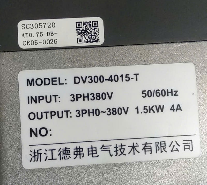
DV300-2015-T) được thiết kế đặc biệt để hoạt động ở tần số cao, thường dùng cho các ứng dụng như trục chính tốc độ cao (Spindle).Biến tần DV300 có nhiều model khác nhau, được xác định bằng mã sản phẩm (ví dụ: DV300-2015-T – 1.5kW), nhưng thông số kỹ thuật chung thường bao gồm:
| Thông số | Giá trị điển hình (Tùy Model) |
| Điện áp vào (Input Voltage) | 1 Pha 220V hoặc 3 Pha 380V |
| Điện áp ra (Output Voltage) | 3 Pha (thường bằng điện áp vào) |
| Tần số ra (Output Frequency) | 0.00 Hz – 400 Hz (hoặc cao hơn đối với dòng tần số cao) |
| Phương pháp điều khiển | Điều khiển V/F, Vector vòng hở (SVC) |
| Tích hợp phanh | Tích hợp bộ hãm (Braking Unit) cho một số công suất/model |
Để sử dụng và cài đặt biến tần DV300 một cách hiệu quả, tài liệu bạn cần là:
5.2 Functions and parameters table
| Function code | parameter | Setting range | Factorysetting | not e | |
| Pr000 | frequencysettings selection | 0: Main freq. input is set via operator panel1: set by panel potentiometer;2: set by potentiometer on terminal FV or 0~10V;3: set by 0~10mA signal on terminal FI4. set by ▼▲ on operation panel. Ifpotentiometer and 0~10V signal aredetected from terminal FV, thisparameter will shift to 5automatically;5. set by potentiometer on terminal FVor 0~10V; if operation on ▼ ▲ isdetected, this parameter will shift to 5automatically. | 4 | √ | |
| Pr001 | runningcommand selection | 0. controlled by operator panel(startforward rotation, start reverse rotation,stop);1. controlled by external terminals(start/stop, forward rotation/reverse
terminals(start/stop, forward rotation/reverse stop); |
4 | × |
| Pr002 | 0. stop by decelerating brake;1. free stop;2. immediate DC brake. | 0 | √ | ||
| Pr003 | Reverseforbidden setting | 0-reverse allowed 1-reverse forbidden | 0 | × | |
| Pr004 | forbid to startreverse rotation from keyboard | 0. allow to start reverse rotationfrom keyboard1. forbid to start reverse rotationfrom keyboard | 1 | × | |
| Pr005 | startup frequency | 0.0~10.0Hz | 3.0Hz | √ | |
| Pr006 | delayed startup | 0.0~60.0S | 0.0S | × | |
| Pr007 | accelerating anddecelerating curve | 0. straight line;1. S curve. | 0 | × | |
| Pr008 | automatic voltage stabilization | 0. ineffective;1. moderate sensitivity;2. high sensitivity. | 220V:1 308V:2 | √ | |
| Pr009 | slip frequency compensation | 0.0~5.0Hz | 0.0Hz | √ | |
| Pr010 | carrier frequency setting | 1~15KHz (△ ) | △ | × | |
| Pr011 | frequency arrival setting | 0.0~400.0Hz | 0.0Hz | √ | |
| Pr012 | 0.analogy frequency meter 1.analogy voltage meter 2.analogy current meter | 0 | √ | ||
| Pr013 | 50~200% | 100 | √ | ||
| Pr014 | Startup display item selection | 0. frequency (H,L);1. output current (A);2. bus-bar voltage (U);3. number of users;
|
0 | √ |
| Pr015 | proportional coefficient ofmechanical speed | 0.01~99.99 | 30.0 | √ |
| Pr016 | data protection | 0. modification allowed;1. modification forbidden. | 0 | √ |
| Pr017 | rememberfrequency | 0. the frequency set by ▲ and ▼ onoperator panelwill not beremembered;1. the frequency set by ▲ and ▼ onoperator panelwill beremembered. | 1 | √ |
| Pr018 | immediate restart after instantaneous power failure | 0. ineffective;1. automatically follow rotatingspeed in case of power-on;2. restart from startup frequencyin case of power-on. | 0 | √ |
| Pr019 | 1~10 times | 0(ineffective) | √ | |
| Pro020 | waiting time of restarting after malfunction | 0~10S | 10S | √ |
| 220V Inverter: 350-400V, factory setting: 360V; | Pro021 | startup voltage of brake | 360V | √ |
| 380V Inverter:650-700V, factorysetting:660V. | 660V | |||
| 220V inverter: 350-450V, factory setting: 400V; | Pr022 | response point preventing overheat while decelerating | 400V | √ |
| 380V inverter: 650-750V, factory setting: 700V. | 700V | |||
| Pr023 | 110~150% of rated current of inverter
|
130 | √ |
| Pr024 | response pointpreventing over-current at constant speed | 110~150% of rated current of inverter | 130 | √ |
| Pr025 | rated current ofinverter | △ | ◎ | |
| Pr026 | rated current ofmotor | 50-110% of rated current of inverter | 100 | √ |
| 220V inverter: 50-250V, factory setting: 220V; | Pr027 | rated voltage of motor | 220V | × |
| 380V inverter: 100-450V, factory setting: 380V. | 380V | |||
| Pr028 | rated frequencyof motor | 20.0-400.0Hz | 50.0Hz | × |
| Pr029 | intermediatevoltage | lowest voltage-99% of rated voltage | 18 | × |
| Pr030 | middle frequency | 0.1~rated frequency of motor | 12.5Hz | × |
| Pr031 | lowest voltage | 0~10% of rated voltage of motor | 1 | × |
| Pr032 | torque elevation | 1~30 (△ ) | △ | √ |
| Pr033 | highest operation frequency | the lowest operation frequency~400Hz | 50.0Hz | √ |
| Pr034 | the lowestoperation frequency | 0.0Hz~10.0Hz | 0.0Hz | × |
| Pr035 | analog inputcorresponding to highest frequency (maximum PID target value) | 0~100% | 98Hz | √ |
| Pr036 | analog inputcorresponding to the lowest frequency (minimum PID target value) | 0-100% | 2 | √ |
…